
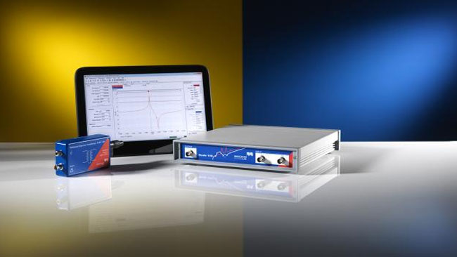
Bode 100 Vector Network Analyzer & Frequency Response Analyzer
1. Vector Network Analyzer
The vector network analyzer function of the Bode 100 allows you to measure:
- Swept S-parameters in the 50 Ohm system
- Reflection coefficient and return loss
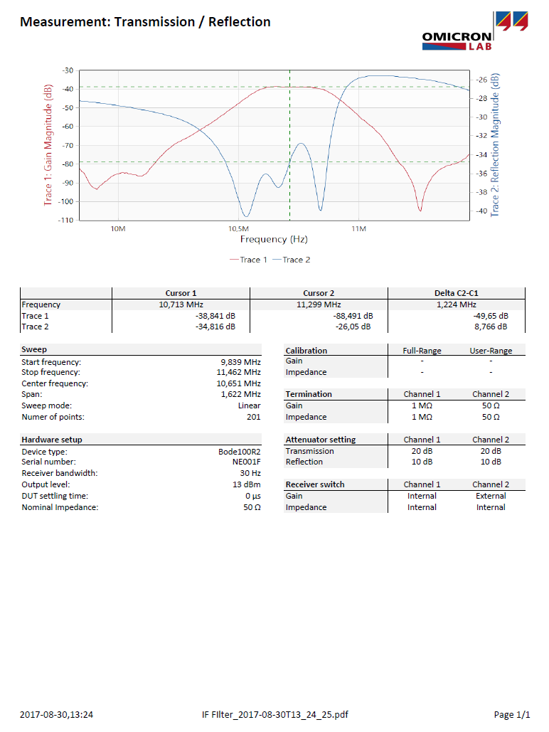
- Insertion loss of filters
- Group delay characteristics
- Influence of termination on amplifiers

2. Frequency Response Analyzer
The Bode 100 serves as a Gain/Phase meter and is ideally suited to measure:
- Transfer functions of electronic circuits
- Stability of control systems such as DC/DC converters or voltage regulators
- Power Supply Rejection Ratio (PSRR) respectively Audio Susceptibility

3. Impedance Analyzer
The Bode 100 offers you a high variety of impedance measurement possibilities to easily analyze:
- Electromagnetic devices such as transformers and inductors
- Capacitors and their parasitics
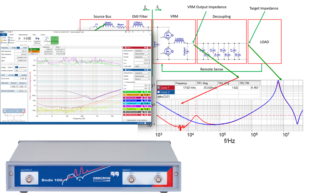
- Input impedance and output impedance of electronic circuits
- Resonance frequency of RFID, NFC and wireless power systems
- Impedance of power delivery networks (PDN)
Your Benefits
With the Bode 100 you get an exact picture of your electronic circuits and components in a frequency range from 1 Hz to 50 MHz
- One device for multiple applications
- Accurate measurement results
- Simple setup – fast results
- Easy data processing
- Automated measurements

Technical Data – Bode 100 VNA Revision 2
Technical Data Sheet – Revision 2
Technical Data Sheet – Revision 1 (2005 – 06/2017)
| Characteristic | Rating |
|---|---|
| Frequency range | 1 Hz to 50 MHz |
| Waveform | Sinusoidal |
| Signal level range | -30 dBm to 13 dBm 0.007 VRMS to 1 VRMS (at 50 Ohm load) |
| Source level accuracy | ± 0.3 dB (1 Hz to 1 MHz) ± 0.6 dB (1 MHz to 50 MHz) |
| Source level frequency response (flatness) | ± 0.3 dB (typical, referring to 10 MHz) |
| Frequency accuracy after adjustment | ± 2 ppm ? quantisation error ( = 0.5 ? step size ) |
| Frequency stability | ± 2 ppm (< 1 year after adjustment) ± 4 ppm (< 3 years after adjustment) |
| Frequency step size / resolution | 0.00605 Hz (1 Hz to 100 Hz) 0.03632 Hz (100 Hz to 50 MHz) |
| Source impedance: | 50 Ohm |
| Return loss (1 Hz to 50 MHz) | 30 dB, > 35 dB (typical) |
| Spurious signals & harmonics | < -55 dBc (typical) |
| Connector type | BNC |
| Characteristic | Rating |
|---|---|
| Frequency range | 1 Hz to 50 MHz |
| Input impedance (software switchable) | High: 1 MO ± 2% || 40…55 pF Low: 50 O |
| Return loss @ 50 O input impedance | 28 dB, > 35 dB typical (1 Hz to 50 MHz) |
| Receiver bandwidth – RBW (software selectable) | 1 Hz, 3 Hz, 10 Hz, 30 Hz, 100 Hz, 300 Hz, 1 kHz, 3 kHz, 5 kHz |
| Noise floor (S21 measurement) RBW = 10 Hz, PSOURCE = 13 dBm, Attenuator CH1: 20dB, CH2: 0dB | 1 Hz to 10 kHz: -115 dB (typical) 10 kHz to 10 MHz: -125 dB (typical) 10 MHz to 50 MHz: -105 dB (typical) |
| Input attenuators (software selectable) | 0 dB, 10 dB, 20 dB, 30 dB, 40 dB |
| Input sensitivity / range | 100 mVRMS full scale @ 0 dB input attenuator 10 VRMS full scale @ 40 dB input attenuator |
| Input channels dynamic range | 100 dB (@ 10 Hz RBW) |
| Gain error | < 0.1 dB (User-Range calibrated) |
| Phase error | < 0.5° (User-Range calibrated) |
| Connector type | BNC |
| Connector | Type B |
PC Requirements
| Processor | Intel Core-I Dual-Core (or similar) |
| Memory (RAM) | 2 GB, 4 GB recommended |
| Graphics resolution | Super VGA (1024×768) higher resolution recommended |
| Graphics card | DirectX 11 with Direct2D support |
| USB interface | USB 2.0 or higher |
| Operating system | Windows 7 SP1 or higher |
AC/DC Power Adapter
| Input voltage/frequency | 100…240 V/47…63 Hz |
DC Power Requirements
| Input voltage range / power | +9…24 V / <10 W |
| Supply current | at 12 V: 580 mA (typical) at 18 V: 390 mA (typical) at 24 V: 290 mA (typical) |
| Low supply voltage shut-down | 8.25 V (typical) |
| Power connector / socket | Coaxial power socket Inner diameter 2.5 mm Outer diameter 5.5 mm |
| Connector polarity | Inner connector … positive Outer connector … ground |
Environmental Requirements
| Characteristic | Condition | Rating |
|---|---|---|
| Temperature Range | Storage | -35…+60ºC/-31…+140ºF |
| Operating | +5…+40ºC/+41…+104ºF | |
| For specifications | 23ºC ± 5ºC/73ºF ± 18ºF | |
| Relative Humidity | Storage | 20…90%, non-condensing |
| Operating | 20…80%, non-condensing |
| Dimensions (W x H x D) | 26 x 5 x 26.5 cm 10.25 x 2 x 10.5 inch |
| Weight – Bode 100 | < 2 kg/4.4 lb |
| Weight – Accessories | < 0.5 kg/1.1 lb |
| Characteristic | Rating |
|---|---|
| DC supply voltage | +28V |
| DC supply reverse voltage (device doesn’t work) | -28V |
| Maximum input signal at CH1 or CH2 (low impedance, 50 Ohm) | 1 W (= 7 VRMS) |
| Maximum AC input signal at CH1 or CH2 (high impedance, 1 MOhm) | 50 VRMS 1 Hz to 1 MHz 30 VRMS 1 MHz to 2 MHz 15 VRMS 2 MHz to 5 MHz 10 VRMS 5 MHz to 10 MHz 7 VRMS 10 MHz to 50 MHz |
| Maximum DC input signal at CH1 or CH2 (high impedance, 1 MOhm) | 50 V |
| Maximum return power at the OUTPUT connector | 0.5 W (= 5 VRMS) |
Bode 100 VNA Manuals & Documents
| Name | Description | Version | Date | Size |
|---|---|---|---|---|
| Bode-100-User-Manual-ENU10060508 | User manual for Bode 100 and BAS 3.25 | ENU1008 | 2021/12/22 | 10MB |
| Bode-100-Quick-Start-Guide-ENU10060304 | Quick Start Guide for Bode 100 and BAS 3.X | ENU1008 | 2021/12/22 | 2MB |
| Bode-100-User-Manual-ENU10060506 | User manual for Bode 100 and BAS 3.24 | ENU1006 | 2021/02/10 | 10MB |
| Bode-100-Quick-Start-Guide-ENU10060301 | Quick Start Guide for Bode 100 and BAS 3.X | ENU1006 | 2021/02/10 | 2MB |
| Bode-100-User-Manual-ENU10060506 | User manual for Bode 100 and BAS 3.22 | ENU1006 05 06 | 2019/12/04 | 10MB |
| Bode-100-User-Manual-ENU10060502 | User manual for Bode 100 and BAS 3.11 | ENU1006 05 02 | 2017/08/14 | 9.14MB |
| Bode-100-User-Manual-ENU10060501 | User manual for Bode 100 and BAS 3.00 | ENU1006 05 01 | 2017/04/13 | 9.02MB |
| Bode-100-Quick-Start-Guide-ENU10060301 | Quick start guide for Bode 100 and BAS 3.00 | ENU1006 03 01 | 2017/04/13 | 8.61MB |
| Bode 100 Product Brochure V4-1703 | Bode 100 product brochure | V4 – 1703 | 2017/04/13 | 447.95kb |
| B-WIT-Brochure-V1.1-1403 | B-WIT 100 product brochure | 1.1-1403 | 2014/03/23 | 220kb |
Remark:
If you are still using Bode Analyzer Suite 2.X, feel free to download the old user manual below.
| Name | Description | Version | Date | Size |
|---|---|---|---|---|
| Bode 100 User Manual (Low Resolution) | User manual for Bode 100 and BAS 2.X | AE.4 | 2011/01/23 | 4.00MB |
Bode 100 VNA Software
Frequency Sweep Measurements
Bode Analyzer Suite makes frequency sweep measurements an easy task. Impedance, Reflection, Admittance, Group Delay, Gain and Phase can be measured from 1Hz to 50MHz. Define start frequency, stop frequency and number of points to generate linear or logarithmic frequency sweeps. Cursors help you to find resonance frequencies or zero crossings in the measured curves.

Smith, Polar and Nyquist Charts
Results can be displayed in various formats such as Magnitude, Magnitude (dB), Phase (rad), Phase (°), Real, Imaginary, etc… Besides normal x-y diagrams, Bode Analyzer Suite also offers Polar, Nyquist and Smith diagrams. All diagrams support full cursor and zooming functionality.

Fixed Frequency Measurements
Besides frequency sweep measurements Bode Analyzer Suite also offers fixed-frequency measurements. The result can be displayed in either cartesian or polar form. Series and parallel equivalent circuit parameters are calculated during measurement and updated immediately.

Memory Curves
Use the one-click memory curves to display the change of your DUT in one single graph! Memory curves can be renamed and re-styled according to your needs. Cursors can be attached to a memory curve to read the values of the memory traces.

Startup Screen
Use the startup screen to quickly set-up the Bode 100 according to your needs. All supported measurements are listed in the startup screen. To learn more about the measurements that can be performed with Bode 100, check out the next tab on this page…

Pre-defined measurement modes make measurements simpler and ensure correct device setup and connection setup. The Bode Analyzer Suite offers a high variety of measurement modes to perform Transmission/Reflection, Gain and Impedance measurements using the Bode 100.
Vector Network Analysis
Transmission/Reflection Measurement
Measure S-Parameters S11 and S21 in the 50 O domain or Gain with 1 MO impedance.

Gain/Phase Measurement
Measure Gain/Phase respectively voltage transfer function using two input ports. Input port impedance is software-selectable (1 MO or 50 O).

External Coupler Measurement
Measure reflection/impedance using an external amplifier in conjunction with an external coupler.

Impedance Analysis
One-Port Impedance Measurement
Measure reflection/impedance of a one-port DUT connected to the output port of Bode 100.

Impedance Adapter Measurement
Measure impedance of passive THT or SMD components using the impedance test fixtures B-WIC or B-SMC.

Shunt-Thru Measurement
A measurement configuration very sensitive for low impedance values and therefore suitable to analyze low-impedance devices such as ESR of ceramic capacitors.

Series-Thru Measurement
A measurement configuration very sensitive to high-impedance. Suitable for high-impedance measurements such as piezo-element characterization.

Voltage/Current Measurement
Voltage/Current equals Impedance. This setup is very flexible and especially suitable to measure input impedance and output impedance of active circuits such as DC/DC converters.

Hardware Setup
Configure Bode 100 according to your needs! The hardware setup helps you to configure the device hardware and connection setup correctly. You can switch the input impedance from 50 O to 1 MO and enter external probe factors or adjust the receiver attenuation/range.

Reporting and Documentation
With the Bode Analyzer Suite it is easy for you to create a one-click pdf report on your measurement, including all relevant device settings and measurement curves. You can also copy and paste the diagrams directly into a word processor like Microsoft Office Word. Furthermore all measurement values can be exported to a .csv file or .xslx file for further processing in any spreadsheet application or math program. In addition Bode Analyzer Suite 3.0 or newer support direct Touchstone file export.
Note: You can save every measurement to a .bode3 file. It contains all measurement data, calibration and device settings for archiving and/or sharing measurements. Bode-files can be analyzed with the Bode Analyzer Suite even if no Bode 100 hardware is connected.
Interactive User Interface
Bode Analyzer Suite features an interactive user interface with cursors and cursor grid that show cursor values and special calculation results. Use the cursors to find minima and maxima in the curves or any specific values.
All diagrams can be zoomed and optimized to automatically adjust the axis scaling to the measurement results.

Gain and Impedance Calibration
You want to compensate the cables or the measurement setup? The Bode Analyzer Suite offers THRU calibration for the Gain/Phase measurements and OPEN SHORT LOAD calibration for impedance/reflection measurements. You can apply all necessary settings in the calibration window, the calibration state is shown graphically.

Some measurements have to be repeated over and over again …
… therefore we added an Automation Interface to the Bode 100 right from the beginning. Today many customers are already using this Application Programming Interface (API) to build automated measurement setups involving the Bode 100.
Bode 100 can be controlled from any COM (OLE controller) compliant programming language such as:
- MATLAB®
- C#
- VB.NET
- Excel® with VBA
- C++
- TCL
- Python®
- Delphi®
In addition there is a LabVIEW® instrument driver available for download from www.ni.com.
Bode Analyzer Suite 3.0 or newer features the latest Automation Interface version 3.X that comes with several new features and advantages.
Find out more about the Bode Automation Interface 3.X by having a look at the Automation Interface Reference.
The Automation Interface is included in the Bode Analyzer Suite installer. Check out the Bode 100 download area.
Trademarks
- LabVIEW® is a registered trademark of National Instruments Corporation.
- MATLAB® is a registered Trademark of The MathWorks, Inc.
- Excel® and Visual Basic® are registered trademarks of Microsoft Corporation.
- Python® is a registered trademark of the Python Software foundation
Support
Bode Analyzer Suite 3.25 SR2 (2023-08-29)
The Bode Analyzer Suite installer provides the graphical Bode Analyzer Suite (BAS) user interface as well as the COM based Automation Interface (AI).
PC Requirements
| Processor | Intel Core-I Dual-Core (or similar) |
| Memory (RAM) | 2 GB, 4 GB recommended |
| Graphics resolution | Super VGA (1024×768) higher resolution recommended |
| Graphics card | DirectX 11 with Direct2D support |
| USB interface | USB 2.0 or higher |
| Operating system | Windows 7 SP1 or higher |
Note: New Automation Interface V3.X
Attention: BAS V3.X comes with a completely new Automation Interface! If you have developed an automated solution with a previous version of the Bode Analyzer Suite you will have to apply some changes if you want to use the BAS V3.X!
The new Automation Interface 3.X brings several advantages to you:
- Compatibility with the new Bode 100 Hardware-Revision 2
- Use the predefined measurement modes of Bode Analyzer Suite
- Control more than one Bode 100 from one PC
- Perform faster measurements (especially single-point measurements)
- Use events to build real-time applications
- Fully compatible with 32 bit and 64 bit Microsoft Windows systems
- Directly access the Automation Interface from .NET
- Access from multiple programming languages via COM
To learn more about the new Automation Interface 3.X, check out the Automation Interface reference at:
www.omicron-lab.com/BodeAutomationInterfaceHelp
In addition there is a LabVIEW® instrument driver available for download from www.ni.com
| Name | Description | Version | Date | Size |
|---|---|---|---|---|
| Application | Bode Analyzer Suite (Full installer 32 bit & 64 bit) | V3.25 SR2 | 2023-08-29 | 251MB |
| Application | Bode Analyzer Suite – 32 Bit (32 bit installer only) | V3.25 SR2 | 2023-08-29 | 115MB |
| Application | Bode Analyzer Suite – 64 Bit (64 bit installer only) | V3.25 SR2 | 2023-08-29 | 122MB |
| Application | Bode Automation Interface – Automation interface only (32bit & 64bit) | V3.25 SR2 | 2023-08-29 | 196MB |
OMICRON Lab Terms & Conditions
The Bode Analyzer Suite 3.25 brings several new features that allow you to: Plot transfer functions over frequency as Bode plots or Nyquist plots etc. Compare measurements with theoretical transfer functions using our new Expression Traces. Evaluate complex mathematical expressions using measurement data and memory data.
By downloading and installing the software from OMICRON Lab, you agree to the download terms and conditions as well as the End User License Agreement (EULA). Please read the respective documents before downloading and installing OMICRON Lab software.
If you do not agree with these agreements and conditions, do not download the software.
EULA – Download Terms & Conditions – Uninstall Information
If you agree with these terms and conditions of use, proceed by clicking on the links below.
Please check out the system requirements needed to run Bode Analyzer Suite!
Newest Stable Version
Note: Bode Analyzer Suite V3.X and V2.X cannot be installed at the same time on a PC! (This also applies to the automation interface.)
Bode 100 VNA Accessories
| Model | Description | Price |
|---|---|---|
| B1666600 (Recommended) | PML 111O Passive 10:1 Probes (Qty 2) | $460.00 (Qty 2) Add to Cart |
| P0005758 | B-WIT 100 Wideband Injection Transformer | $590.00 Add to Cart |
| P0005759 | B-SMC Impedance Adapter | $690.00 Add to Cart |
| P0005760 | B-WIC Impedance Adapter | $690.00 Add to Cart |
| E1399000 | Bode 100 Carrying Case | $120.00 Add to Cart |
| P0005772 | B-AMP 12 External Power Amplifier | $1,050.00 Add to Cart |
| P0005773 | B-LFT 100 Low-Frequency Injection Transformer | $790.00 Add to Cart |
| P0005778 | B-LCM Low Frequency Common Mode Choke | $590.00 Add to Cart |
| P0005774 | B-RFID-A For Class 1 Cards | $130.00 Add to Cart |
| P0005775 | B-RFID-B For Class 3 Cards | $130.00 Add to Cart |
| P0005776 | B-RFID-C For Class 6 Cards | $130.00 Add to Cart |
| P0001108 | B-RMK-10 Rack Mount Kit | $210.00 Add to Cart |
Bode 100 Vector Network Analyzer
Get an exact picture of your electronic circuits and components in a frequency range from 1Hz to 50 MHz.
- ★
- ★
- ★
- ★
- ★
If I could have one instrument for my power supply test lab, it would be a VNA
Steve Sandler
CEO of Picotest and PI Guru
The Bode 100 is not only a state-of-the-art Vector Network Analyzer, it also works as:
- Impedance Meter
- Frequency Response Analyzer
- Gain Phase Meter
- Sine Wave Generator
- ★
- ★
- ★
- ★
- ★
The Bode 100’s compact design hides its powerful capabilities. Its portability and accurate measurements make it my go-to solution for assessing component performance in both lab and field settings
Robert D
Test Engineer