
Non-invasive Stability Measurement
What is Non-Invasive Stability Measurement (‘NISM’)?
Control loop stability is critical to the performance of all systems, as it influences all closed loop parameters, as well as system noise. Unfortunately, in many instances, particularly in the cases of voltage references, fixed voltage LDOs, and integrated POLs, a Bode plot assessment is not feasible because there is no feedback loop access to the part. In other cases, the feedback loop is difficult to access because the hardware is integrated or would require cutting a PCB trace.
In yet other cases, the devices either contain multiple control loops, with only one of them being accessible, or the order of the control loop is higher than 2nd order, in which case the Bode plot is a poor predictor of relative stability. A further complication is that in many portable electronics, such as cell phones and tablets, the circuitry is very small and densely populated leaving little in the way of access to the control loop elements.
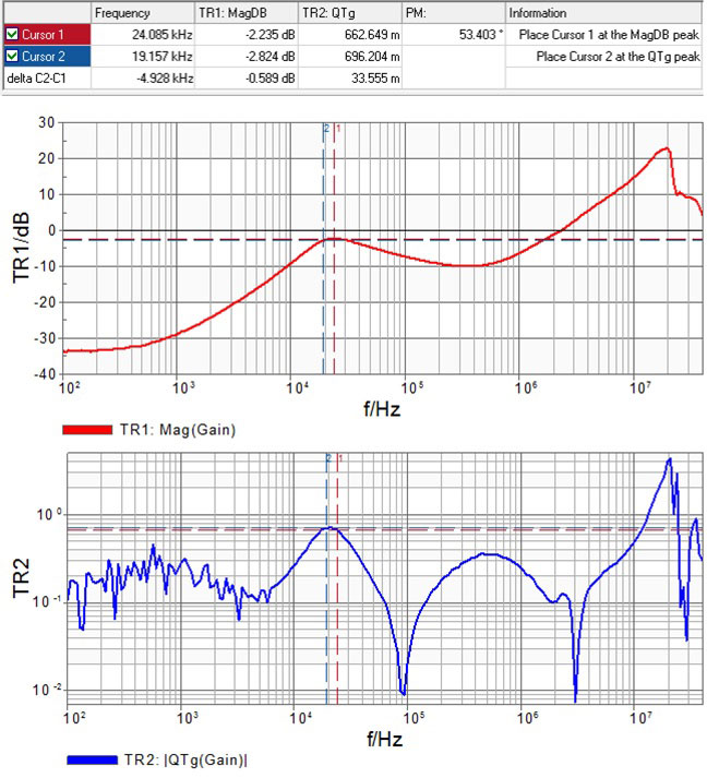
In these cases, the non-invasive stability margin (‘NISM’) assessment, which is derived from easily accessible output impedance measurements, is the only way to verify stability. Click here for a list of test methods and equipment that you can use to measure impedance which utlize Picotest Probes.
Videos
Non-Invasive Stability Measurement
Non-Invasive Stability Measurement – Control Loop Analysis When You Can’t Get to the Loop
Introduction to NISM – Non-Invasive Stability Measurement
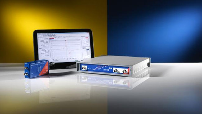
In this video, Steve Sandler shows how to measure control loop stability using the Bode 100 VNA via Output Impedance.
Non-Invasive Phase Margin Measurement of Voltage Regulators using the J2111A Current Injector
Non-Invasive Phase Margin measurement of Voltage Regulators using the Picotest J2111A Current Injector.
The mathematical relationship that allows the precise determination of the control loop stability from output impedance data was initially incorporated into the OMICRON Lab Bode 100 VNA software in late 2011. Now it is available in many VNAs and EDA simulation tools. The mathematical solution is based on minor loop gain theory, which makes it equally applicable to measuring the stability of switching converters with input filters (i.e. Middlebrook stability criteria). This method is simple, precise, and can be performed in simulation and using a VNA to measure either the 1-port reflection impedance or 2-port shunt through impedance. Both of these methods are well established and Bode plot measurements and non-invasive results generally agree to within 1 degree of each up to the approximately 65 degrees.

Products


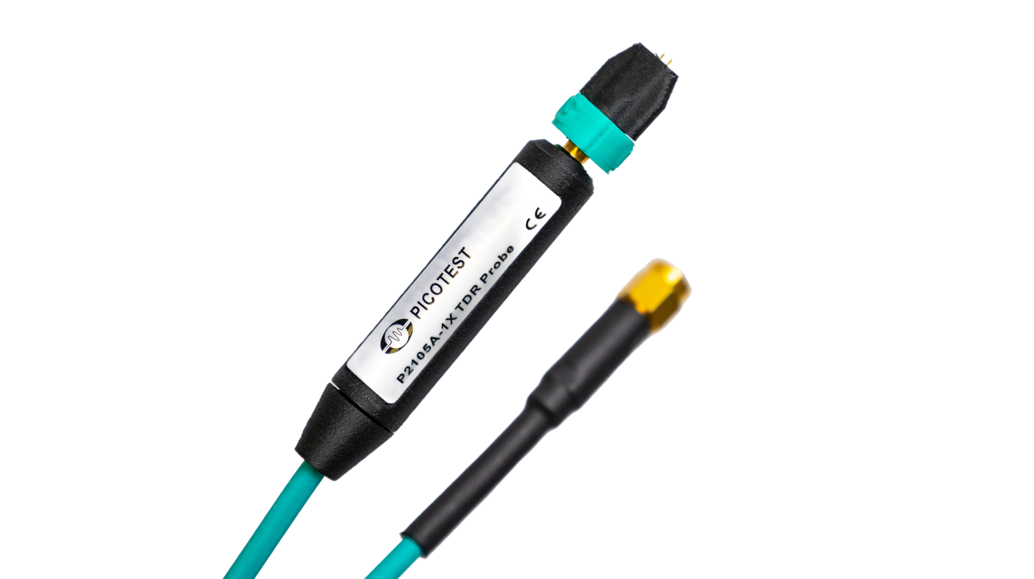
P2105A 1-Port Low Noise TDR – Ripple Browser Probe
Read more: P2105A 1-Port Low Noise TDR – Ripple Browser ProbeArticles & Documents
Load Regulation, Vout/Iout, and Output Impedance
Published October 6, 2023 Masashi Nogawa,, Sr. Member of Technical Staff, Qorvo Published on Microwave Journal.com Masashi’s latest installment of his ongoing blog series…
Keysight and Picotest Release NISM for PathWave ADS
How to Optimize Design with SPICE Simulation: Expert Insights by Steve Sandler May 27, 2023 | Jitter, Noise, PCB, Picotest, SPICE Modelling, Videos, VRM https://www.youtube.com/embed/gLjyZwSDdos This session presents the essential role of…
How to Optimize Design with SPICE Simulation: Expert Insights by Steve Sandler
This session presents the essential role of simulation in the design and development ecosystem. The speaker draws on his own experience and shares some…
Picotest Releases NISM Stability Tool for Cadence PSpice, Keysight ADS Simulators, and Hardware VNAs and Scopes
March 19, 2023, Phoenix, AZ: Picotest.com, a leader in high-resolution test and measurement equipment, has announced the availability of the non-invasive stability measurement (‘NISM’)…
A Bode Plot Without Access to the Control Loop
by Steve Sandler This extreme measurement seems more impossible than difficult. The traditional stability assessment method for voltage regulators is the Bode plot. Access…
App Note: NISM using the P2102A Probe and E5061B VNA
By Benjamin Dannan and Steven Sandler, Picotest.com Control loop stability is critical to the performance of all systems, as it influences all closed loop…
Introduction to NISM – Non-Invasive Stability Measurement with Steve Sandler
In this video, Steve Sandler shows how to measure control loop stability using the Bode 100 VNA via Output Impedance. This test can be…